

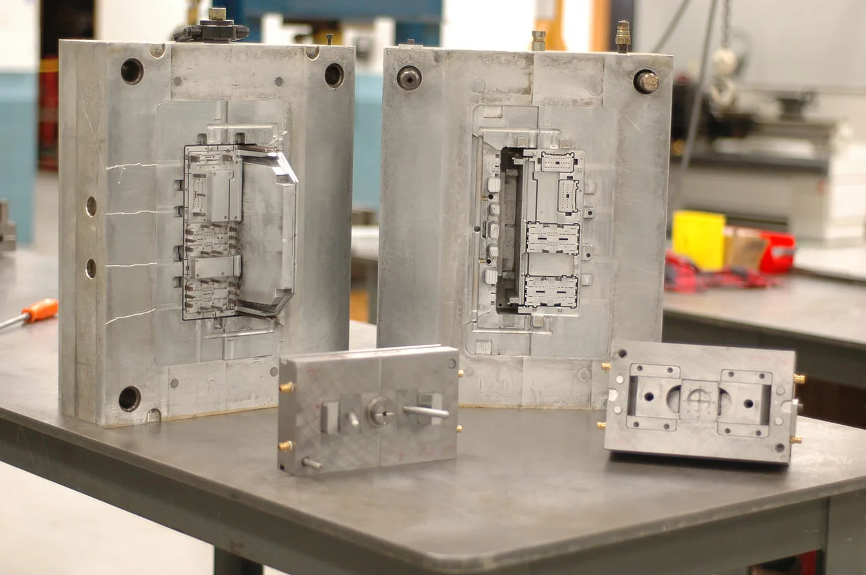
EU buyers can compare tooling suppliers in China and other markets through production calculations, validation evidence and lifetime procurement costs.
A tooling quotation establishes a purchase price. The decisions behind it determine whether a manufacturing programme delivers consistent components, meets demand and protects its margin. For manufacturers in the European Union (EU) sourcing injection molding and stamping dies from China or other markets, the important questions concern output, material behaviour, dimensional stability and maintenance. A mould that produces attractive samples can struggle at production speed. A stamping die that passes its first inspection can become expensive when cutting elements wear prematurely or replacements are difficult to obtain.
Consider an illustrative programme producing 600,000 assemblies annually, each containing one plastic housing and one stamped steel bracket. The two components must fit together, arrive in the correct quantities and meet a common launch date. This creates a useful framework for evaluating tooling as a connected production investment.
ssprecision.com.cn, a tooling supplier based in China, lists both injection molding services for engineered plastic parts and metal tooling. Its moulding portfolio includes thermoplastic parts, insert moulding and overmoulding. Establish project-specific equipment, acceptance criteria and production commitments through quotation and qualification.
All programme volumes, prices, cycle times, clearances, dimensions and financial calculations below are hypothetical examples. They are neither SSP quotations nor guarantees of its performance.
Decision 1: Injection molding and stamping dies start with the assembly
Injection moulding and stamping generally serve different functions within an assembly. A plastic housing may provide electrical insulation, low mass and integrated clips. A metal bracket may provide stiffness, a fastening interface or an electrical connection. Selecting each process separately can leave an expensive mismatch at their interface.
An illustrative 4.00 ±0.10 mm plastic hole paired with a 3.70 ±0.03 mm metal pin has a worst-case diametral clearance of 0.17–0.43 mm. Hole position, bracket flatness, warpage and assembly loads also matter. Specify functional datums and appropriate geometric dimensioning and tolerancing (GD&T) for critical features.
Material specifications need equal precision. SSP lists ABS, PC, PP, PA6/PA66 and POM among its moulding materials. Procurement documents should identify the exact resin grade, reinforcement, colour, permitted regrind and relevant application requirements. For moisture-sensitive grades, agree drying and conditioning requirements using the resin manufacturer’s data. Fibre orientation and processing conditions can affect shrinkage; a generic material label is insufficient for predicting final dimensions.[1]
SSP lists SPCC/SPCD steel, SUS304 stainless steel, C1100 copper and C2680 brass for stamped components. Specify grade, temper, thickness tolerance, coating and rolling direction where relevant. Changing sheet strength or condition can change forming behaviour despite identical nominal thickness.
Approve materials and mating interfaces before releasing steel for tool manufacture.
Decision 2: Design injection molding and stamping dies for manufacture
Injection molding design: filling, cooling and ejection
Uniform wall sections help avoid local variations in cooling and shrinkage. Strength often comes more economically from ribs than from adding bulk. Protolabs gives 40–60% of the adjoining wall thickness as a general rib-design guideline.[2] An illustrative 2.5 mm wall with a 1.25 mm rib sits at 50%. Final dimensions still depend on the resin, loading, appearance requirements and tool design.
Draft should be agreed alongside surface texture and ejection. An illustrative 1.5° draft angle is a design input to review, rather than a universal minimum. Gates, weld lines and ejector marks should be positioned with functional and cosmetic requirements in mind. Undercuts may require slides or lifters, adding moving components and maintenance obligations.
Injection molding shrinkage: an 80 mm housing example
Shrinkage illustrates why tool dimensions and component dimensions differ. With an assumed linear shrinkage of 0.6%, a simplified estimate for an 80 mm finished feature is:
Estimated cavity dimension = 80 ÷ (1 − 0.006) = 80.48 mm.
This calculation only illustrates the principle. Actual compensation requires grade-specific data, geometry, flow direction, mould temperature and validation; reinforced materials can shrink differently along different axes.[1]
SSP’s custom injection mold tooling offering includes single- and multi-cavity designs, hot-runner configurations and tooling with slides, lifters and ejection systems. Its website lists P20, H13 and S136 steels. Buyers should request the proposed grade, delivery condition, heat treatment and maintenance rationale for their application. Corrosion resistance, wear resistance and polishability are separate selection considerations.[3]
Stamping dies: strip layout and forming sequence
A progressive die advances a strip through successive cutting and forming stations. After the strip fills the tool, output depends on the number of finished parts released per stroke. Eight stations do not automatically mean eight finished parts per stroke. Compound dies combine operations such as piercing and blanking at one station; transfer tooling moves separate blanks between operations. SSP lists these alternatives within its stamping die design and manufacturing services.
Stamping die material utilisation: a bracket layout example
Strip layout deserves financial scrutiny. Assume one finished bracket occupies 2,500 mm² and its strip allocation is 60 × 55 mm = 3,300 mm². Geometric material utilisation is 75.8%. Reducing the allocation to 58 × 52 mm = 3,016 mm² raises utilisation to 82.9% and reduces strip area consumed per part by 8.6%. This excludes rejects and scrap recovery credits. Any revised layout must preserve carrier strength, feeding reliability and adequate spacing between features.
Decision 3: Injection molding and stamping capacity in accepted parts
Cycle time and press speed describe only part of the capacity picture. Overall equipment effectiveness, or OEE, combines availability, performance and quality. It incorporates stoppages, reduced speed and first-pass quality losses.[4]
For a mould, the ideal hourly rate is cavities × 3,600 ÷ ideal cycle time in seconds. For a stamping die, it is strokes per minute × 60 × finished parts per stroke. Multiplying either ideal rate by an assumed OEE gives a planning estimate of accepted output. Quality losses must not be deducted a second time if they are already included in OEE.
Table 1. Illustrative capacity calculation for the paired component programme
| Planning measure | Plastic housing: injection mould | Steel bracket: progressive die |
| Annual requirement for accepted components | 600,000 | 600,000 |
| Output per cycle or stroke | 4 cavities | 1 finished part |
| Assumed ideal operating speed | 30 seconds per cycle | 60 strokes per minute |
| Ideal hourly output | 480 parts | 3,600 parts |
| Assumed OEE | 80% | 75% |
| Estimated accepted output per planned production hour | 384 parts | 2,700 parts |
| Planned production hours required annually | 1,562.5 | 222.2 |
| Annual planned production time available to the programme | 1,800 hours | 1,800 hours |
| Share of that time required | 86.8% | 12.3% |
The housing process is the capacity constraint under these assumptions. Faster stamping will not increase completed assemblies when plastic housings are unavailable. Instead, it may increase inventory.
A modest moulding cycle change is significant. At 35 seconds, with four cavities and the same 80% OEE, accepted output falls to approximately 329 parts per hour. Producing 600,000 housings then requires approximately 1,823 hours, exceeding the assumed allocation.
Demonstrate cycle time with the intended resin, equipment and acceptance criteria. Agree how changeovers and maintenance enter the production calendar, and confirm that the necessary hours are reserved.
Decision 4: Mould clamping force and stamping die press compatibility
Tooling must fit the equipment on which it will run. A mould trialled in China may later be transferred to an EU plant with different machine interfaces. Agree tie-bar spacing, platen dimensions, mould height, shot capacity, opening stroke, ejector connections and utilities before design approval.
A first approximation of mould opening force is projected area × cavity pressure.[5] Suppose the combined projected area of all cavities and runners is 10,000 mm², with an assumed cavity pressure of 40 N/mm², equivalent to 40 MPa:
Opening force = 10,000 × 40 = 400,000 N = 400 kN ≈40.8 tonnes-force.
This load illustration requires confirmation of clamping margin and complete machine fit. Cavity pressure differs from hydraulic or barrel pressure.
For a simple stamping cut, a preliminary force estimate is cutting perimeter × sheet thickness × shear strength.[6] With an assumed total perimeter of 180 mm, thickness of 1.0 mm and shear strength of 300 N/mm²:
Cutting force = 180 × 1.0 × 300 = 54,000 N = 54 kN ≈5.5 tonnes-force.
Complete press selection also requires simultaneous operations, forming and stripping loads, energy, speed, off-centre loading, shut height and feeding arrangements. A progressive die can cut several features at different stations simultaneously.
Cutting clearance must be specified explicitly. An illustrative 8% of sheet thickness per side equals 0.08 mm per side for 1.0 mm stock, or 0.16 mm total. The suitable value depends on material and edge requirements. Tighter clearance is not automatically better: it can increase stripping forces and wear. Tool trials should establish the appropriate balance between edge quality and tool performance.[7]
Decision 5: Tooling validation, first articles and critical dimensions
Sample approval should establish why the tool is ready for production. A useful acceptance package connects material records, tool drawings, measurement results, process settings and demonstrated output.
For a hypothetical four-cavity mould, measuring five components from each cavity produces a 20-part dimensional set. Repeating that collection over three agreed runs gives 60 measurements per inspected feature, with cavity identity retained. Such sampling can reveal cavity differences; it does not, by itself, establish long-term process capability or constitute a universal acceptance plan.
For the stamped bracket, measure relevant hole positions, formed angles, flatness and burr height. An illustrative burr limit of 0.05 mm, or 50 micrometres, needs an agreed location, orientation and measurement method. Define whether dimensions are assessed before or after any subsequent treatment and whether inspection holds the component in a fixture or measures it freely.
Request CMM or optical reports where appropriate, a ballooned drawing, calibrated measurement methods and functional assembly checks. Distinguish tool manufacturing accuracy from the achievable tolerance of the moulded or stamped component. They describe different outcomes.
SSP’s website describes dimensional inspection and mould trials. Those descriptions support asking for project-specific examples; they do not replace an agreed inspection plan. Automotive programmes may require customer-specific PPAP documentation. Nonconforming samples should trigger documented containment, corrective action and repeat verification before shipment approval.
Production trials should record accepted output, rejects, stoppages and process settings. For the illustrative mould, two hours at the ideal 30-second cycle represent 960 theoretical parts. The accepted count and actual elapsed production time determine whether the trial supports the capacity assumption.
Decision 6: Injection molding and stamping dies over the production life
A lower initial tool price can make commercial sense for limited demand, uncertain product life or a design likely to change. At sustained volumes, cooling, maintainability, material efficiency and downtime can outweigh the purchase-price difference.
The following model compares two hypothetical packages containing both the housing mould and bracket die. Each supplies 600,000 accepted component pairs annually. Costs are assumed amounts in euros, not supplier prices. Variable cost includes component materials and processing; maintenance and disruption are accounted for separately to avoid double counting.
Table 2. Illustrative annual operating-cost comparison for two tooling packages
| Cost measure | Package A: lower initial investment | Package B: higher investment with assumed operating improvements |
| Initial mould-and-die investment | €50,000 | €65,000 |
| Combined variable cost per accepted component pair | €0.82 | €0.76 |
| Annual variable cost at 600,000 pairs | €492,000 | €456,000 |
| Planned annual maintenance | €4,500 | €6,000 |
| Assumed annual corrective repair and disruption cost | €12,000 | €4,000 |
| Total annual operating cost | €508,500 | €466,000 |
| First-year tool investment plus operating cost | €558,500 | €531,000 |
| First-year cost per accepted pair, including tool investment | €0.931 | €0.885 |
Package B requires €15,000 more initially but saves €42,500 annually under these assumptions. Simple incremental payback is €15,000 ÷ €42,500 = 0.353 years, approximately 4.2 months with evenly distributed production. Its first-year saving is €27,500. These results depend on proving the operating improvements and demand forecast; they exclude financing, tax and residual tool value.
To compare China, EU and other sourcing locations, convert quotations to the same EU delivery destination, currency and scope. Add freight, insurance, customs clearance, duties where applicable, commissioning, qualification, inventory and local support to the operating model. Use an agreed Incoterms® 2020 rule with a named place to clarify delivery tasks, costs and risks.[11]
Maintenance planning should identify wear parts, inspection triggers, replacement drawings and responsibility for repair. SSP lists replacement punches, inserts and mold components among its products. Buyers should confirm compatibility, materials, inspection requirements and replenishment arrangements, and consider holding critical spares where production takes place.
EU–China tooling sourcing: drawings, delivery and compliance
EU buyers considering tooling from China should compare qualified candidates in the EU, the UK, Türkiye, India or Mexico against the same drawings and acceptance plan. China can make commercial sense when a supplier offers a suitable tooling concept and a favourable total-cost proposal for a stable programme. Compare engineering support, trial attendance, transport, commissioning and repair access. For an EU production line, nearby repair support or stocked spares may be worth including alongside an overseas tooling contract. Availability and service arrangements need supplier-specific confirmation.
An effective RFQ should give every candidate the same six inputs:
- Product definition: revision-controlled CAD files, drawings, assembly interfaces, datums and critical dimensions.
- Material definition: exact resin or sheet grade, reinforcement or temper, thickness, colour and permitted substitutions.
- Production requirement: annual and lifetime quantities, batch sizes, target output and the intended machine specifications.
- Acceptance evidence: sampling plan, dimensional and functional checks, cosmetic references, material records and trial requirements.
- Tooling and support scope: ownership, authorised subcontracting, design-file access, wear parts, maintenance and transfer arrangements.
- Commercial and delivery scope: EU destination, Incoterms® rule and named place, customs responsibilities, packing, milestones and responsibility for design changes.
Protect intellectual property through agreed confidentiality, drawing access controls and contractual restrictions on unauthorised manufacture. Build the launch plan backwards from installation and qualification, allowing time for trials, corrections, transport and customs rather than treating tool completion as production readiness.
For EU applications, identify applicable REACH obligations and, where components enter electrical or electronic equipment within scope, RoHS material requirements. Obtain evidence relevant to the resin, additives, metals and finishes. CE marking applies only where relevant EU legislation requires it; a moulded housing or stamped bracket does not automatically require its own CE mark.[8–10]
Discuss injection molding and stamping dies requirements with SSP
The value of injection molding and stamping dies becomes clearer when buyers connect functional specifications with accepted output and lifetime operating costs. A supplier discussion should therefore begin with the assembly, production calendar and validation requirements. EU manufacturers evaluating China-based SSP alongside other international suppliers can share drawings, material specifications, volumes and delivery requirements to request a comparable tooling proposal. That makes both the technical commitment and the commercial comparison easier to assess.